|
|
|


|
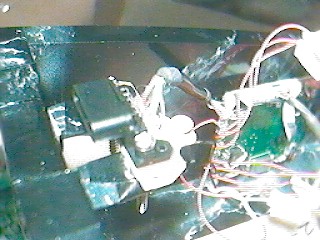
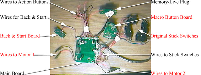
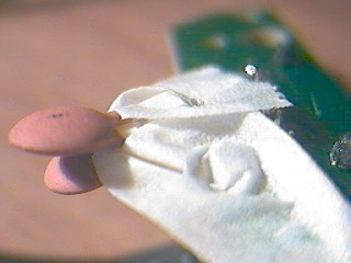
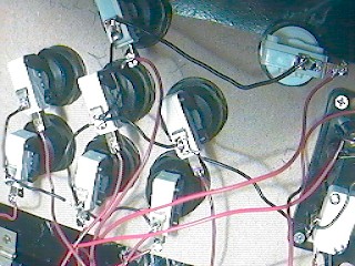
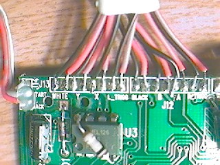
Let's start with the 1st image. These wires all went to the Back/Start board. The White is Ground. This will connect to the Ground connections of all switches (as shown above). If your using a Perfect 360, you can ground it to this as well.
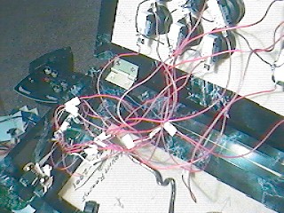
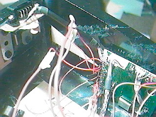
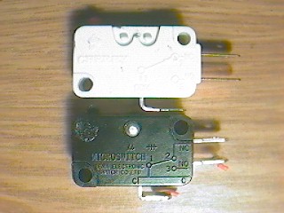
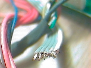
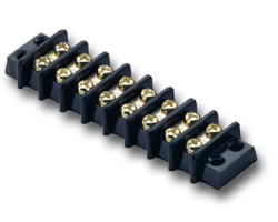
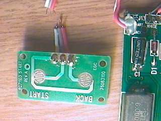
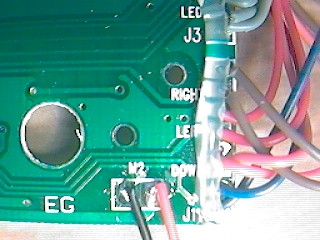
The Grey wire goes to Start, leaving the Red one for Back. The 2nd image shows may Red and Black wires going all over the place. Good news, you don't need any of the Black wires! To make your life easier you may cut the black ones shorter so they don't get in your way. The Red wires are marked pretty clearly. They are: White, Y, X, L, Black, B, A, R. You may want to label these wires since they're all the same color. In the 3rd image you'll see colored wires in set's of two. Brown, Red, Orange, Blue. As before you only need half of these (the others are all Ground). In each pair, it's the 2nd wire that you need. Thus from top to bottom they are: |
| Not Used | (Brown) |
| Right | (Brown) |
| Not Used | (Red) |
| Left | (Red) |
| Not Used | (Orange) |
| Down | (Orange) |
| Not Used | (Blue) |
| Up | (Blue) |
|
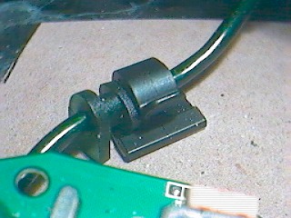
Perfect 360:
Only if your using a Perfect 360 joystick. The Ground connection for the stick is the same as the buttons. You can simply connect the ground wire to the ground on one of your buttons. The Positive wire connects to the Red wire coming out of the gamepad's main cord. This connection can made from the bottom side of the PCB quite easily. | 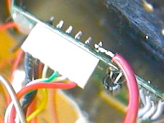 |