Madcatz Xbox GamePad Hack

Update: Unless you already have a madcatz gamepad I suggest using the Reflex hack over this one.
After a few weeks of play testing I've found this hack has trouble with pressing multiple buttons at the same time. Other's have confirmed this issue.
L and R can not currectly be use with this hack.
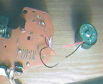
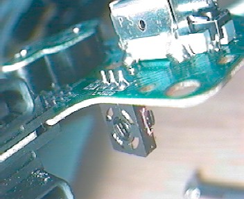
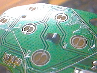
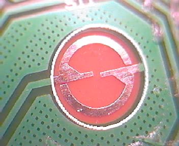
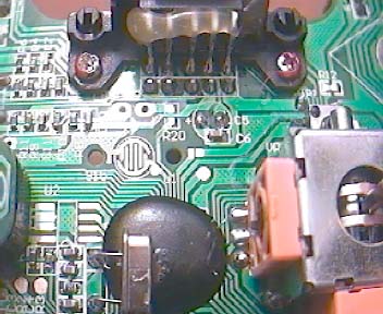
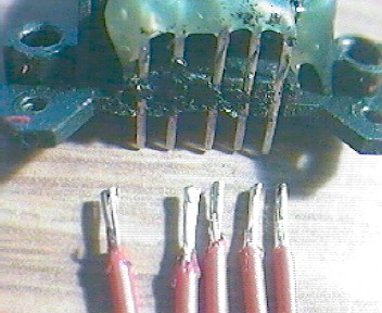
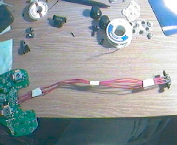
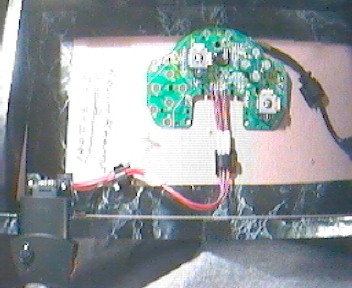
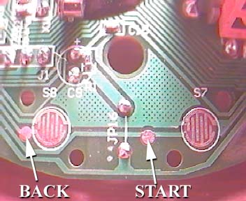
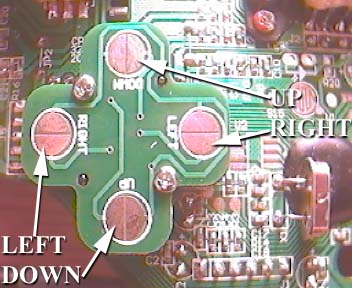
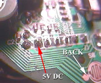
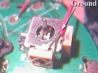
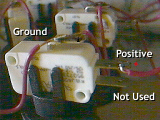
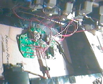
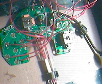
Soldering to the PCB is required.
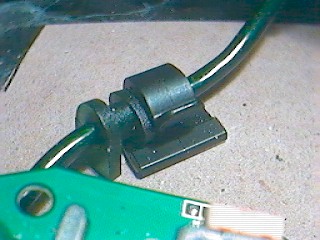
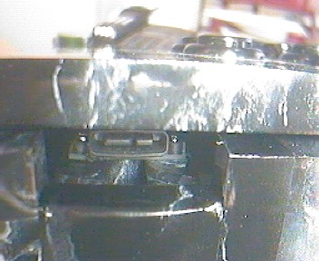
Memory/Live port needs to be extended if you wish to have an external port on your controller.
The Reflex hack does not have the above issues and costs roughtly the same.

On the other hand the madcatz is much more easy to find then the Reflex. It can serve as a good temporary PCB and later replaced. Which is a simple process.

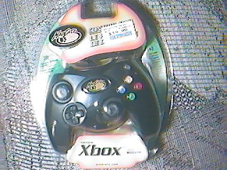
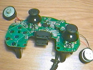
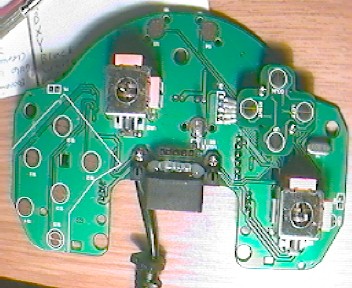
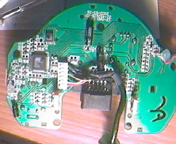
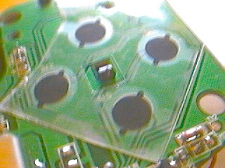
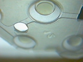
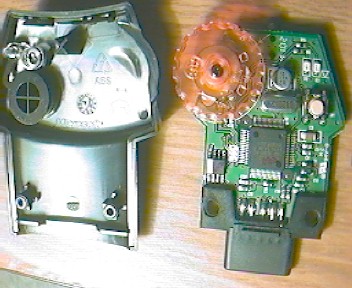
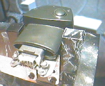
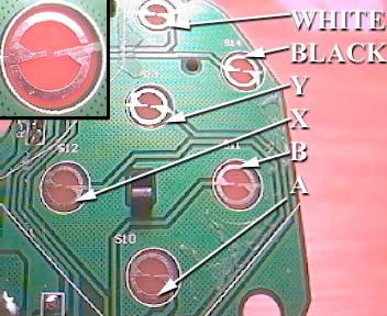
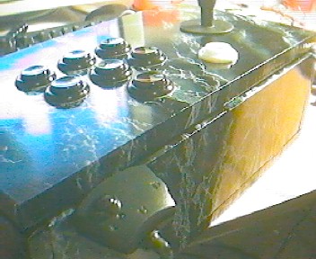
Below are a couple of pics of another model. This one has rubber grips on the handles and a middle button for macros. There is also a LED for the macro button. Either of these pads will work. Most of the differences have little effect on this project. Soldering on this pad is slightly harder due to smaller connections for the buttons. Note the soldering points shown in the images are of the pad without the macro button.

Motors, Analogs and Live!, Oh My!


Well here's what I think about motors. Seriously though you don't need anything rumbling in your box. Cut these loose and do something creative with them later.

While were removing stuff let's get rid of the triggers. These things are held on by screws, tabs AND glue. First remove the screws, then with a small screwdriver or something press the tabs through the holes. Be very careful not to snap the board. Pull each trigger away slowely. Be aware they each have small a tab that fits into a varible resistor. There's also glue holding each trigger to it's resistor but it should give way as you pull.
The resistors are still there and may cause games to think L or R are slightly pressed. These come off easily by pulling on them while heating their connections. Use desoldering braid if they put up a fight.
You'll notice the resisters have three connections. On the board you need to connect two of these together using either a long blob of solder or a tiny piece of wire (See below pic). With the board positioned as if it were a gamepad, connect the top and middle conenctions. If your not sure if you got the right ones note that the remaining connection is Ground. Do this with both L and R.

Currently I do not know of a way to wire up L and R buttons. You Can solder to the blob that you just made but I noticed that A, B and possibly other buttons are activated when this is done. I know this sucks, and I'm looking into it. If anyone finds a way before I do please let me know and I'll update the site.

Over all of the action buttons there is a sheet a plastic. This is glued on but will peel off. Use a small flathead screwdriver or razor blade to get under it. Try to remove as much glue as possible without using any liquids. You'll be soldering this area later and wont want to deal with burning glue.
So while were here let's checkout these buttons. They are quite different from traditional gamepads. The board itself has bare metal contacts (which rocks since we'll be soldering to these). The resistant layer commonly over the contacts is on the plastic sheet. If you look at the rubber button pads you'll see that they are dome shaped. So as you press down harder the dome flattens out causing more of the sheet to make contact with the board's metal. This creates less resistance which the board registers as a harder press.
Simple and effective :)
Well once your done looking at that niffty design you can throw it away since our buttons will be digital. Our connections will be soldered directly to the metal giving no resistance, thus the buttons will act as full force when pressed.

If your me (which your not), you want to kick ass on XBLive. For that were going to need to connect a Live Communicator to this board. However, the board is going to be in a box, which is not going to allow access to the mute and volume controls. I had the idea of obtaining a communicator which would remain forever in this controller and have it's controls wired to a knob and button on the outside of the box somewhere.. Then I opened the thing...

I don't know about you but there's a Lot going on in there! No wonder the thing costs fifty bucks. Even if it could be done how many people (myself included) can get ahold of a second communicator? I still want one for my gamepad.
So, here's an optional step depending on how bad you want to be able to get at those controls. The idea is the make your own port in the box so you can plug in the communicator or whatever else you want in there. Surprisingly there are only five connections for the port. All you have to do is make an extension cord for your port's plug using five wires.

First thing to do is remove the screws holding the plugs in. The top one is going to be the one for Live. Regardless of what you want to do with the other one later they both need to be removed (you may re-attach the other if you want). You will need desoldering braid for this. Lay some braid on top of the whole row of connections and press it with your iron a few times along it's length. You'll probably need to do this a couple times to remove enough solder to get the plug off. Note there's also tabs holding the plugs on the board. Once one plug is off it will expose the connections for the other one. Do the same with that one. Odds are your going to melt some plastic so keep your face away from the smoke and even hold your breath if you must. The row of connections nearest the edge of the board is the one for Live.
Be carful with soldering the extention wires that none of the connections short together. On the plug end be sure to run electric tape between the pins.

For the port in the box you'll need a rectangular hole. In my case I had the box already built (I retired it from the DC) so this was a bit tricky. I highly suggest you make this before building. A couple of L-brackets and some screws will hold it in place.

Preparing the board


A few things of note on this board. For one, at least on mine, the d-pad buttons are all labeled incorrectly. Maybe when these things are made this makes some kind of sense. For what were doing, left is left and up is up.

You'll need a Ground connection as well. You can use any of the non-used connections on the d-pad or the metal casing of either analog stick for this (as shown).

This board wires up in typical fashion. You'll need a wire soldered to each point shown in the images (except the 5V if you do not have a Perfect 360 Joystick), as well as the Ground wire mentioned above.
Perfect 360 Users, use the 5V DC point to power your stick. This is from the Red wire coming from the controller's main cord. For Ground use the same one that everything else is using.

Control Wiring

Once your controls are mounted simply run wire(s) to all of the Grounds on each of them and connect that chain to the Ground on the board. Connect a wire from each point on the board to the corresponding control's Positive.
You may also want to use a couple wire clamps. These can help keep wires in place. You want to be sure none are involved with the joystick's moving parts. Shown here I've clamped the main cord at it's rubber stopper to prevent a pulled cord from ripping apart my soldered connections. If you don't use a clamp here a simple knot where it exits the box will do.

Completed Stick


Copyright © Kevin Reems 2003