Microsoft Sidewinder Hack
Preparing the board
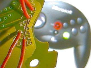
First thing to do is take appart the game pad. This is just a matter of unscrewing some screws and removing the board.
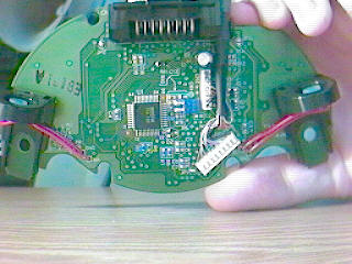
Nothing too scary. There's a lot of similar projects like this online that will have you solder your wires to the button contacts. This requires scraping the contact, clamps, and a pain in the ass. Microsoft was kind enough to give us holes for each button on this board. So that hassle won't be necessary. However, this won't be really easy either..
As you can see these are pretty close together. If this seems harder to you then maybe try soldering to the contacts. It's up to you.
While were still examining the board. Cut a short piece of wire, strip both ends and bend it in half. Open the propertise for the SideWinder in Control Panel (You do have it installed right?). See that GND hole in the left image with the wire going into it? That's going to be ground for everything in your joystick. Touch one end of the wire to that and the other end to one of the letter'ed holes. Amazing, it lights up on the screen. This is the basic idea behind the whole thing. This bent wire will soon be replaced with buttons and your joystick.
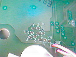
Before you go poking around, note the following holes will not be used (INTXA may even freeze up the control panel window):
BL (right image) There are two of these. The one with the arrow pointing to it should be avoided. Use the other one.
BR (left image) There are two of these as well. Use the one next to GND. It's easier to get to.
INTXA (right image under all the wires) This is not used at all.
MO (left image) Is optional. This is for the mode button. Odds are you'll never need this. Considering it's right in the middle of everything, why bother?
So let's get down to business. Close control panel or it will bitch when you unplug the pad which you need to do. From here on out if you want to test a connection using the control panel you'll have to plug in the pad, test, unplug the pad. You should do no soldering while it is plugged in. The reason being, if a hunk of solder lands on something causing a short while power is in the board you may be kissing it goodbye. I've seen this sort of thing happen (I had a tiny screw nuke a laptop motherboard), so trust me on this.
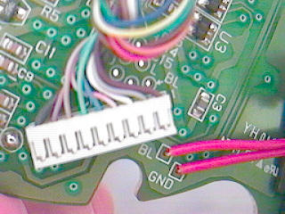
For my project I'm not connecting the buttons and stick directly to the board. Instead I'm placing a connecter between each part and the board. This is to make assembly (and any future disassembly) easier. This is optional but I recommend it. The rest of this page will assume your doing the same.
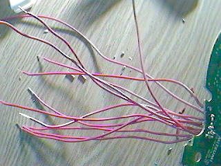
Now's a good time to turn on your solder iron. It can heat up while you cut yourself a bunch of wires about 5 inches long. Strip both ends. It's important you strip both ends now. You don't want to be yanking on the wires while they're attached to the board. Also don't attach the connecters to the wires yet.
So you've got a hot iron and a lot of wires. Let's remove the BL and BR (trigger) buttons since we'll need the connections their using. Heat their connections till the solder melts and pull the wires out.
First solder your ground wire. Since this will be required to test any other connections. You may want to use a slightly longer wire for this one as well.
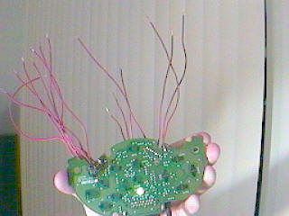
Continue to solder the rest. Make sure you do these in an order that won't screw you later. If you don't have the board flat, make sure it's tilted so that any excess solder falls away from your other connections.
Control Wiring
Run a gound line to everything. This will be many short wires connecting each part. Let your iron heat up while you cut and strip many 3 inch wires. Optionally you could use one long wire with the coating striped every 3 inches. Whatever's easier for you.
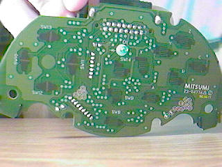
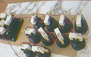
Each micro-switch has three connecters. There's only two we care about. The one on the bottom is Ground. The other one closest to it will close when the button is down (which is what we want). The last one is closed when the button is Not down (which we don't care about).
Connect your ground wires up in a chain. You can see in the picture that my chain starts at the joystick, goes around all the stick's switches, then hops over to the buttons, criss-crossing them all. In the event a lot of buttons fail to work this makes it easy to trace the problem if it's a ground wire. For example, if the joystick works, but none of the buttons do. Then we know there's a problem with the wire hopping from the stick to the buttons.
I went ahead and connected all these grounds without soldering (stuck the wire into the hole). Then went back and soldered them all.
Now all you ahve to do is connect the wires fro mthe board to each switch.
Completed Stick
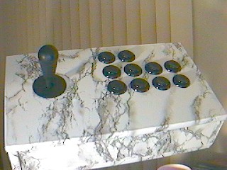
And here's the finished Controller!
Because this is based off a Sidewinder, it has all the features of a Sidewinder. It's fully programmable, can emulate the keyboard and can be daisy chained with up to three more of these (or real sidewinders).
As you can see there's a lot of buttons on this thing. Because this is primarily for fighting games I wanted to be able to use this for Capcom and SNK games. By having a block of 8 buttons, the left 6 can be used for Capcom games and the top 4 for SNK/Neo Geo games. There's two more buttons as well. These are mainly used as Pause and Start, but like any button, they can be set to anything.
Copyright © Kevin Reems 2003
